Getting Started!
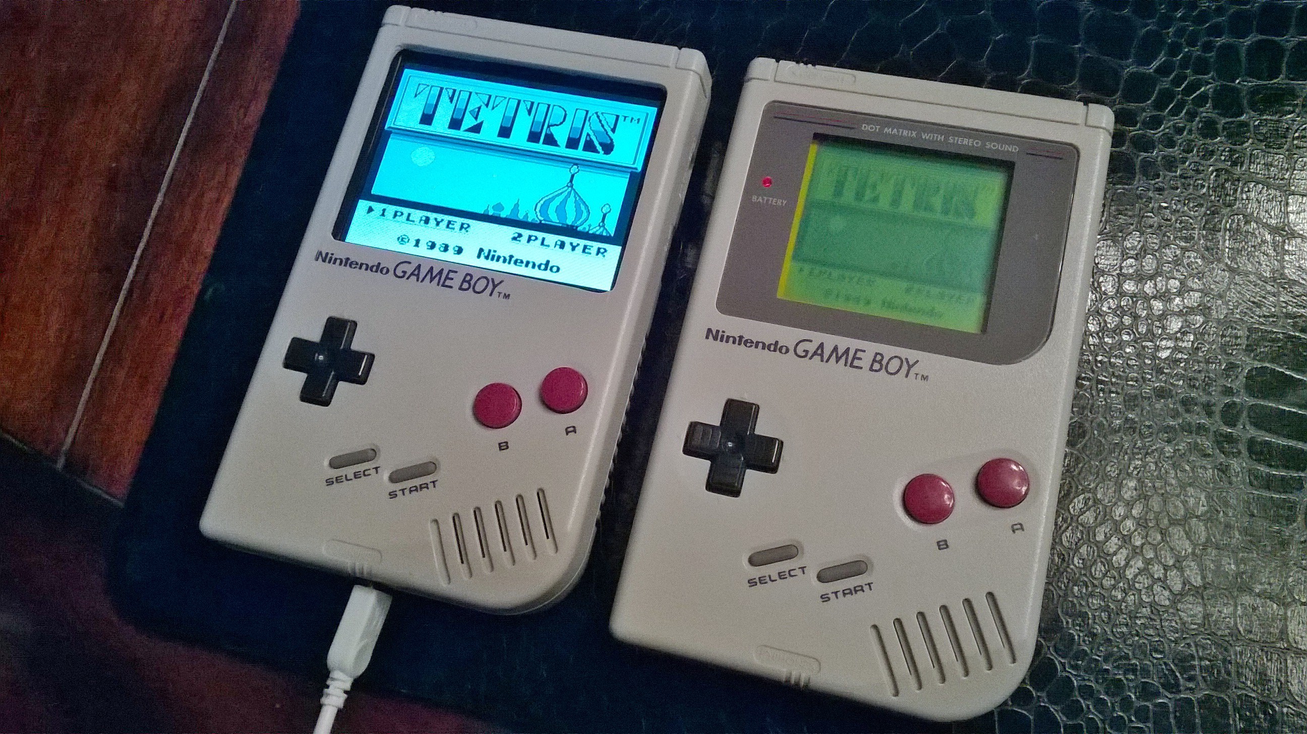
I had recently bought an original Gameboy DMG from Good Will for a whopping $5.00, condition unknown. Taking a gamble, I purchased it and took it home to find that it had severe damage caused by a battery that exploded and leaked all over the mainboard.
I had also recently started looking on eBay for the elusive Gameboy Light. It’s a system I have always wanted but could never allow myself to buy since they are pretty expensive on eBay. The Gameboy Light is the Gameboy Pocket with an Indiglo light and was only released overseas in Japan.
I had bought a Raspberry Pi a while back and really didn’t know what I wanted to do with it. At that moment, like a Reese’s Peanut Butter cup, it dawned on me – could the Raspberry Pi be used with a Gameboy?
The Raspberry Pi is a small ARM based computer that fits in the palm of a normal adult hand. The great thing about the Pi is that it has several ways to connect I/O for video, audio, network, USB as well as a direct I/O set of pins called the GPIO pins.


After doing some research, I came to the conclusion that this project might actually be conceivable. Everything I needed was there, it was a matter of getting things together and working out the hardware as well as software side of things. That’s where this guide comes in. It’s my attempt to pass on what I’ve learned as well as taking you through the various steps I took to make it a reality. First off, the parts…
The Parts List
Hardware
- Pi Model B
- 3.5″ LCD Backup Screen
- Controller PCB
- 3 Watt Audio Amplifier
- Rear Buttons
- Power Switch
- Female to Male Micro USB Cable
- Broken Gameboy DMG (please don’t sacrifice a perfectly good working one)
Software
Tools
- Tri-Wing Screwdriver for Gameboy Case
- Dremel
- Soldering Iron
- Solder
- Wire Cutters
- Electrical Tape
- Hot Glue Gun
- Electrical Wire
- Exacto Knife
- Patience…
The Case
The first thing that had to be done was to see if the Pi would even fit into the case. I found that the Pi sits almost perfectly on the back case of the Gameboy. The width of the Pi fits snug down the center of the case, but in order for it to fit, some modifications had to be done to the case itself.
Using a Dremel, I cut out a most of the battery compartment as well as some posts that on the case for the LCD that would no longer be needed. Doing so, the Pi sits flush with the back of the DMG case:

In the picture above, the battery compartment is on the left and the cartridge slot is on the right. I had to cut back the Cartridge slot as well in order to allow the GPIO pins to fit.
I had initially cut a slot on the left thinking I would add a wireless keyboard or network dongle which can still be added. This would use additional power which means more drain on the battery so those were left out.
LESSON LEARNED – given that, I probably should have de-soldered the Network and USB ports to slim up the Pi which would have allowed for more room to work with.
The Screen
The screen was the first challenge. The screen runs off 12V out of the box which wouldn’t work with the USB battery pack. The USB battery pack is rated at 5V, 1000mAH so the goal was go modify the screen to allow it to run at 5V.
Luckily, there is a great thread here: http://www.raspberrypi.org/forums/viewtopic.php?f=41&t=17651 which details how to modify the PCB for the screen to run at 5V instead of 12. The problem with these screens is that there seem to be several versions of the PCB controller boards which require different approaches.
For my particular setup, the board came with the 4 wires (yellow, white, black and red) all soldered onto the PCB. I found a board in the thread above that matched my board, but I still had some difficulties getting the board to run off of 5 volts.
I finally got it to work by removing the power converter chip as well as soldering a jumper between the + power in and the capacitor on the top right as seen below:

The next step was to hook a composite input to the screen PCB board. For this, I took a composite wire I had and stripped off the connector to create a smaller connector that would fit into the Pi’s female composite port. The Pi composite input could have been de-soldered, but I chose this approach to allow it to be unplugged from the Pi if needed.
The Yellow wire from the LCD Controller is soldered into the Composite input. The Black wire (ground) is soldered from the LCD Controller board as well and then wired to the male composite connector. You can see the connector on the left side of the image below
 After this was completed, the screen and Pi were plugged into a 5V USB input and tested.
Success!
The next challenge was fitting the LCD and controller board to fin in the case. I initially wanted to keep the size of the original Gameboy window and add on a new screen protector. I tried orienting the screen in a portrait layout, but this proved problematic with Retropie.
Editing the root “config.txt”, you have the ability to rotate the screen as well as adjusting the overscan of the screen. The config.txt file can be edited directly from your SD card with any PC. Here is a handy guide to the various settings that can be tweaked and adjusted in the config.txt: http://elinux.org/RPiconfig
None of the adjustments made yielded a layout that would fit correctly within the Gameboy’s window. I made the decision to go ahead and cut out the window to allow the screen to be displayed.
This also meant that I would have to layout the screen in a landscape orientation. This would not work without some trimming of the LCD Controller board since it’s wider than the width of the Gameboy. The parts outlined in red below are what needed to be cut to get the board to fit.

After multiple cuts and trims, I found that I was able to BARELY fit the Controller Board into the case. It only fits because part of the controller board sits in the position where the original Gameboy Contrast knob used to sit. However, it does fit!


For the LCD, I used black electrical tape to cover up the silver border of the screen. Once this is done, I used some double sided stick padded tape and trimmed it to form a border around the LCD and then mounted it to the case.
The Controls
After getting the screen to work, the next step was to get the controls to work. I decided that I would try to use the Pi’s GPIO inputs instead of getting something like a Teensy board. Adding another board would mean that I would have to find room in the cramped DMG case and the GPIO pins are already there, waiting to be used!
I stumbled on a company that creates Controller boards for DMG Gameboy’s that works perfectly with this setup. Instead of having to take the original Gameboy PCB, cutting it and having to solder in wires, the Kitsch Bent PCB allowed me to solder directly to inputs built right into the PCB.
Below is the Controller PCB. The PCB screws into the existing Gameboy mounting posts so the original buttons and rubber fit right in like the stock board would fit. The arrow points to the solder points with each point clearly marked off with it’s respective control function. This makes it easy to associate a control to a solder point which was tied to a specific GPIO pin.
The other advantage of this was that the Kitsch Bent version uses a common ground. This meant that I only need one ground wire for all of the buttons.
Initially I had bought some wires with female to female connectors that I thought I could just plug into the GPIO pins with. This proved to be a failure since the wires sat too high and could not be bent. I decided to strip the wires and solder them directly to the GPIO pins. This proved to be a mistake that caused me unneeded work and issues when trying to assemble everything together.

LESSON LEARNED – I should have bought a GPIO ribbon cable similar to this: http://www.adafruit.com/products/1337. This would have been a simple plug and go solution instead of the pain of soldering the wires to the pins and having them pull off as I tried to work around things.
Once the pins were all soldered to each of the wires, it was time to setup the Retrogame program that would handle each of the input controls.
I followed this guide https://learn.adafruit.com/retro-gaming-with-raspberry-pi/buttons which details the steps needed to map a GPIO input to a corresponding keyboard key. I mapped out the keys based on the following which worked out great for all of the inputs I needed:


Once the program was updated, I compiled the updated version of the code and added the entry to autostart as the Pi booted. I had to make a couple of adjustments for the ESC key in Retropie and had to double map the A button to on the Gameboy to be an S on the keyboard as well since the PC Engine emulator seemed to want to use the keyboard S key as one of it’s buttons.
I also decided that I needed some extra controls since I intendedto run the Gameboy Advance emulator as well which would need shoulder buttons. I decided to mount to buttons I found at Radio Shack that would work.
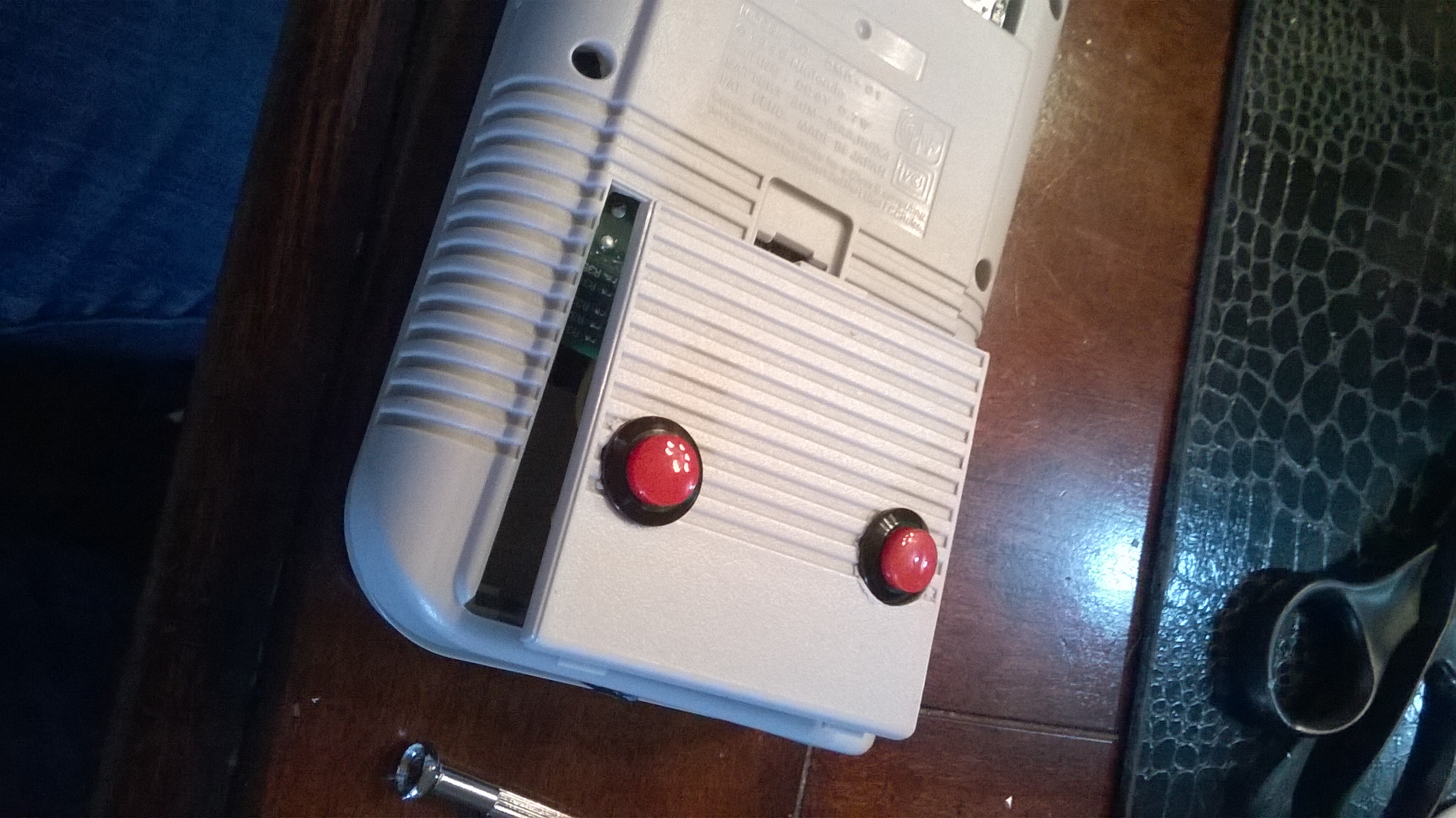
The position of the buttons seems to work better than putting them on the side. My middle fingers fall onto these buttons with the natural grip of the DMG case which works great. These buttons also map to the Page Up/Page Down keyboard keys which I use for paging back and forward through the ROM lists.
For these buttons, these each needed their own ground so I used some of the free GPIO ground pins for each. You can see these in the GPIO mapping diagram above.
Audio
The first thing I had to do was figure out a way to connect to the Pi’s audio out port. I considered de-soldering, but utltimately found that I could just take an old pair of earphones and cut the Input Jack’s rubber shielding to expose a pin with 2 solder points that I could wire to. This allowed me to use an Earphone Jack to essentially plug into the Pi’s audio out jack without desoldering anything. Doing this, I wired directly to the speakers at first only to find that the sound was… lacking!

I ended up ordering an Audio Amplifier board from eBay (above) and connected it to the Pi’s Audio out. The Audio Amplifier requires 5 Volts of power to run, so I soldered wires from the LCD Controller Board’s Positve solder point to the +5V/Ground of the Audio Amplifier.
I wired in the wires from the Pi’s Audio out to the RIN/GND (bottom left of the Audio Amplifier board) and then wired the speaker to the R+/R- (top left of Audio Amplifer board). This drastically improves the loudness of the speakers.
I had originally wanted to use the Gameboy’s Sound Control potentiometer, but it was impossible to find a way to mount and I ended up just scrapping that idea.
Retropie includes a Volume adjustment bar in it’s menu so that’s how volume is controlled.
The Emulators
This was somewhat simple and can be summed up with one word – Retropie. You can download bootable image which can be written to an SD card which will provide you with the Raspian operating system as well as it auto booting to Retropie. Check out the Retropie forums for more details on installing, configuring and troubleshooting Retropie.
Wiring the Beast Together
Here is the wiring schematic for how everything was tied together:
 The battery is connected to a Female Micro USB port that I hot glued into place. I modified the port where the Headphone jack was located widening it so that the Female Micro USB adapter would fit.
(1) The Female Micro USB Positive (RED) wired is then fed to the On/Off Switch. From the switch, the Positive (RED) wire is soldered to the positive solder point on the LCD Controller Board.
The Ground (BLACK) from he Micro USB port is wired directly to the negative solder point on the LCD Controller board.
(2) The Positive (RED) and Negative (BLACK) wires are then wired from the Positve/Negative points on the LCD Controller board and then wired to the Micro USB Male pin that is plugged into the PI.
The Audio Amplifier is also wired to the Positive/Negative points on the LCD Controller Board. The Positive (RED) wire is connected to the +5V solder point on the Audio Amplifier and the ground (BLACK) is wired to the GND right above the +5V solder point on the Audtio Amplifier. Since the LCD is power in runs through the switch, anytime the switch is flipped, the LCD, PI and Audio Amplifier are all turned on or off at the same time.
(3) For video, the positive Composite wire (YELLOW) is wired to the positive solder point on the Composite connection plug. A Negative (BLACK) wire is also soldered between the LCD Controller board and the solder point on the Composite connection plug.
(4) The audio Amplifier is connected to an Audio input jack by connecting the Positive (LIGHT BLUE) and Negative (BLACK) to the GND and RIN solder points on the Audio Amplifier.
(5) the R+ is wired (ORANGE) to one solder point on the speaker and the R- (GREEN) is wired to the other solder point on the speaker.
Overview Videos
Part 1:
Part2:
Final Thoughts…
I love my “Super Mega Ultra Pi Boy 64 Thingy”! It was a lot of fun to build and was well worth it. I recommend just taking your time and doing some research before just jumping in. I’ve tried to layout as much as I could above, but if you have any questions, please leave them in the comments below!
Also, if you build your own version of this project, I would love to see it as well!
Thanks for reading…
Helpful Links
- Raspberry Pi Gameboy Pocket Documentation – AMAZING Pi Gameboy Pocket mod with some excellent build details
- The GamePi Gameboy Case Mod
- Game Boy PC
- PiBoy Advance
- RasppiBoy
- Adafruit Soldering Guide

Brilliant build, well done! I have a couple of broken Gameboys lying around and so might give this a go!
LikeLike
You’re awesome.
LikeLike
What type of battery did you use?
LikeLike
This is awesome! Great work! Thanks for documenting this.
LikeLike
I’ve just had a glimpse of your article, and will give my raspberry the same life! Well done! 🙂
LikeLike
http://www.xodustech.com/projects/raspberry-pi-gameboy-pocket
LikeLike
Um, that red wire jumper wire you soldered on the board goes to a 470uf electrolytic CAPACITOR, not a resistor as stated. Other than that it looks good ! Well done !
Cheers
LikeLiked by 1 person
You are absolutely correct (I even incorrectly spelled RESISTOR as RESISTER!?!) I have updated with the correct term, thanks for pointing that out!
LikeLike
It amazes me that you could attach a screen with such a weird connector to the Pi and get it working.
I want to do this with a camera too, do you think it could work? Like this one: http://www.amazon.co.uk/420TVL-Peephole-Camera-Home-Security/dp/B00DDGHF5G/
LikeLike
I want one. I need one. Where can I buy one? Or can somebody make one for me?
LikeLike
I am very impressed. Nicely done!
LikeLike
How long the device lasts on a fully charged 1000mAh battery pack?
LikeLike
Wow. This is amazing ! Keep it up. Really impressed by the way you fit all the stuff into the small body of the gameboy
LikeLike
You are amazing man! Thanks for the inspiration 😀
LikeLike
Hi, I’m writing about this mod for FastCoLabs and wanted to ask you a question or two. Can you email me?
LikeLike
Hey, I try to rebuild it, BUT I have problem with the programming.
Maybe you can help me,
Thanks
(maybe you e-mail me ^^)
LikeLike
Can you upload a image of your SD.Card??
LikeLike
Hi Lars,
look here: https://gist.github.com/mp911de/968610d1ff9ce7db5c18
You’ll find in the gist the most important settings for EmulationStation and the RetroPie image/Emulators.
LikeLike
Very cool modification. So pushed me into build a similar one, but one question is still open. What kind of battery do you use? Thx for the dokumentation
LikeLike
WOW, you put a computer inside a case, aren’t you soo special. I’m so glad you got so much attention, it’s not this shit hasn’t been done before… OH WAIT, 90’s fuckboy have been putting their oh-so revolutionary raspberry pi inside a hollowed out gameboy, so I have no idea how the hell anyone find your “game boy mod” to be newsworthy. Enjoy prettying up your little bird-shit computer, it won’t get you anyone. Learn to use gentoo.
LikeLike
Trump, is it you ?
LikeLiked by 1 person
Hello microbyter, my Name is Arndt, I coming from Germany. BIG BIG thanks for this awesome project and great documentation! Your idea of “Super Mega Ultra Pi Boy 64 Thingy Build” was an inspiration for me and I started to build my own. Since yesterday it’s finished and: it works fantastic! I’ve documented my build and process as german tutorial on my blog (with pictures) and will be glad for a revisit and comments from your side (and other people, too 😉 ). Please take a look: http://blog.braier.net/2014/08/projekt-raspberry-pi-gameboy/
LikeLike
I have follow the wiring guide and I am not getting any response from the PCB that I have wired to the GPIO, any chance I could get a little more explanation, or I could send info as to what I have done incase I have missed a step.
LikeLike
You have nice job! It’s additional source of inspiration for my project. I have some tips and questions below. Do not get me wrong – I do not complain, I made small write-up to describe things which I see. This is only my opinion – you have right to disagree with me.
“LESSON LEARNED – given that, I probably should have de-soldered the Network and USB ports to slim up the Pi which would have allowed for more room to work with.”
No! It’s waste of money and resources! You should consider Raspberry Pi model A first! Only one disadvantage is amount of RAM, Ethernet and one USB is missing by default. By the way – how you set memory split? I bet that model A could be useful, maybe for PSOne and Nintendo 64 emulation it could be not enough but running this emulators haven’t any sense with 4 buttons input/output.
“Kitsch Bent PCB allowed me to solder directly to inputs built right into the PCB”
As for me it’s a bit overpriced and extremely expensive for those who living overseas. But nice idea. As I see you have pain with wires, you could buy right angle pin headers and ribbon cable as you mentioned or simple jumper wires. I think you used to thick wires – they are 22 or 24 GWA?
“I also decided that I needed some extra controls since I intendedto run the Gameboy Advance emulator as well which would need shoulder buttons. I decided to mount to buttons I found at Radio Shack that would work.”
You could use housing for Gameboy Advance, PSP or Nintendo Dual Screen. It’s no problem to purchase it separately from ebay. If first Gameboy housing for you was perfect – you could buy only buttons with electronics from psp, nds or ga – they also widely available. Six button design allows to emulate more platforms without compromises.
LikeLike
Pingback: https://www.paluch.biz/blog/117-raspiboy-raspberry-pi-gameboy-superpiboy-i-created-mine-here-s-how-to-create-yourself-one.html
LikeLike
Looking over all the instructions before jumping in, I have a few questions. If you prefer to e-mail back and forth, that would be great, as I could keep in touch to let you know how it goes as well as ask more questions. I would like to use the cable you talked about for the controls, however, I am curious on how to use rear buttons like yours?? How would I achieve these buttons to map?? Is there a way to NOT include the rear buttons and some how use the integrated buttons to keep it more “OEM” looking per say? Great idea you have and a great project for me to work on!
LikeLike
Awesome o.o I wanna try to build it =D
LikeLike
Excellent job! I’ve actually made two of these but not in such a small case, one in an old Coleco and the other in an Entex game. Battery life is an issue on both of these so I really like your idea to bypass the regulator chip on the LCD controller. I wasn’t aware you could do this! Can you expand on it a little? I would like to do the same mod on mine.! (giving you full credit)
LikeLike
oops, nevermind about replying back as I saw the web link. THanks for mentioning this in your post!! Awesome
LikeLike
Do you have any changes to suggest if one was to use the Raspberry Pi 2 model?
LikeLiked by 1 person
I have exactly the same doubt. I’m very interested on it: building the total portable emulator using and old Game Boy.
LikeLike
Hey. I was ascinated by this guide and decided to give it a try. Atm i’m collecting all the parts. I ordered a touchscreen designed for the raspberry pi, as i’m not an expert i like to ask: do you think it is possile to wire everything, that i can use the touchscreen as well as the normal gameboy controls? Thanks!
LikeLike
Hello!
Are your back buttons normally open or close?
Thanks
Natalia
LikeLike
you can buy replacement cases without having to have a donor gameboy
LikeLike
Not sure if anyone’s brought this up yet, but RetroPi might be very fun with something like this – compatible with basically every emulator ever.
LikeLike
I am very impressed by your guide and the fact that it worked 100% perfectly! I am so interested in getting into this, I love computers and tinkering with them beyond just the software point. Perhaps one day I will give it a go. Thank you for posting this guide! Please ignore any rude comments you get – people get jealous easily when someone does something creative.
LikeLike
Wow! I am impressed by this! Whenever I get the chance, I am so buying the pi computer – I love tinkering with computers beyond just the software standpoint. Thank you for posting this guide! I also love the website of the manufacturer of the small arm computers, I will be looking more into that. Please ignore any rude comments you may get – people get jealous so easily when they see someone do something that they cannot. Retro gaming and Modding knows no limits. 😀
LikeLike
Hey! Your Super Pi Boy inspired me to make my own! I used different sources for the parts, but everything I did was directly inspired by your build, which, in my opinion, is the best build I’ve seen so far. I did some things different, like four face buttons and four back buttons, and an internal battery. The one problem you didn’t address in your build log, and the problem I’m struggling with, is: how did you get the two halves of the shell to affix to each other? By removing the extra bulk from the battery compartment and removing the bezel to accommodate the larger screen, all of the original screw points are also removed. How did you resolve this issue?
Anyway, here’s two video overviews of my project:
LikeLike
Hi! Nice build! I was just wondering how you get that display so sharp? I have the same one and the resolution is not correct. I have been making changes to config.txt with overscan and framebuffers, but it’s still very fussy. Can you perhaps post your config? 🙂
LikeLike
Do you think this would work with a gameboy colour case, if i got rid of the network and usb ports?
LikeLike
Absolutely fantastic – we have added you to our website @ http://www.arcadepunk.co.uk and gave you 100% skill!
LikeLike
Well I trimmed the edges on the LCD board like you’ve shown in your instructions and now the LCD won’t power on. I must have cut a trace maybe I don’t know
LikeLike
I Don’t know anything about puting things together so im hoping that you will start selling them
LikeLike
I have started construction of this project. Ordered the Rasp Pi 2 model which i think i may have to remove the USB ports and HDMI port that come on it though…not sure how that’s going to work. Having trouble finding the female to male micor usb cable though.
LikeLike
Hi I was just wondering what connector did you get the wire for the female composite port on the pi? Is it off of the monitor because I thought there were female ports on the led monitor. thanks for the cool build
LikeLike
You gave me inspiration to make a similar mod. Thx for that!
I’ve combined this tutorial with that from xodustech.
So the screen is smaller but the battery larger 😄
The version I’ve made has wifi and external usb so I can communicate and update the rpi, if needed.
Once again thx!
LikeLike
Could you use a Raspberry Pi 3b?
LikeLike
This is really great. I ordered a Raspberry Pi 3 with intent to build a small retro gaming station for my boys and I, but now plan to use your build (and a few others) as a guide.
I found a few places online where I can buy replacement Gameboy shells for around $15, so I plan to use one of those with my RPi 3.
Thanks for the inspiration!
LikeLike
I have find my gameboy case on Aliexpress, in fact it’s more easy and the case is perfect !
LikeLike